|
|
Frequently Asked Questions
for Ethernet Power Controllers
Last Updated 02/08/2011.
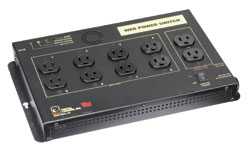
Web Power Switch II Frequently Asked Questions Support? Like to order? Call now (408) 330-5599. What is the
current firmware version?
Question: What is the default IP address? How do I reset to defaults? What is the default password? Answer: If you have lost the IP address or admin password, follow this procedure to reset to the default IP address of 192.168.0.100:
The default master login is "admin" and default password is "1234". This procedure resets the admin login and IP address and lockout, but doesn't affect outlet names and links. Question: On initial setup, I can't establish a Ethernet communications from a Windows PC. Help! Answer: If your default Windows settings won’t access the controller, use a crossover cable and follow these steps to reach the controller’s IP.
Question: Can you explain the auto-ping settings? Answer:
Number of times the ping has to fail (in a row) on a given device before it is power cycled. Number of times to attempt power cycling before giving up and disabling auto-ping.
Question: How can I control the switch from my
own applications?
Question: Can you
develop custom firmware for my application? Answer:
Gladly. We've done this for many customers. Our programming rate is $75/hour.
After we agree on a -very specific- project description, we can send you an estimate of the time
involved to code, debug and test.
Question: Can you develop custom hardware
for my application? Answer:
Gladly. We've done this for many customers. Please call with your requirements Question: What are the current and voltage
ratings? Answer:
Voltage input is 90-240VAC auto sensing. Total current is limited to 15A by circuit breaker. Question: Do
you support PowerMan? Answer:
Yes, absolutely. The latest code is added to the tarball. Download
the latest User Utility here.
If we haven't answered your questions here, please call (408) 330-5599 or send
us an email. We'll be glad to help. © Digital Loggers, Inc. 2005. |