Open Source WiFi PLC
A complete bill of materials for the PLC as well as detailed schematics are provided to encourage development. The demo source code is on Github. Here's a binary image. Let's look under the hood:
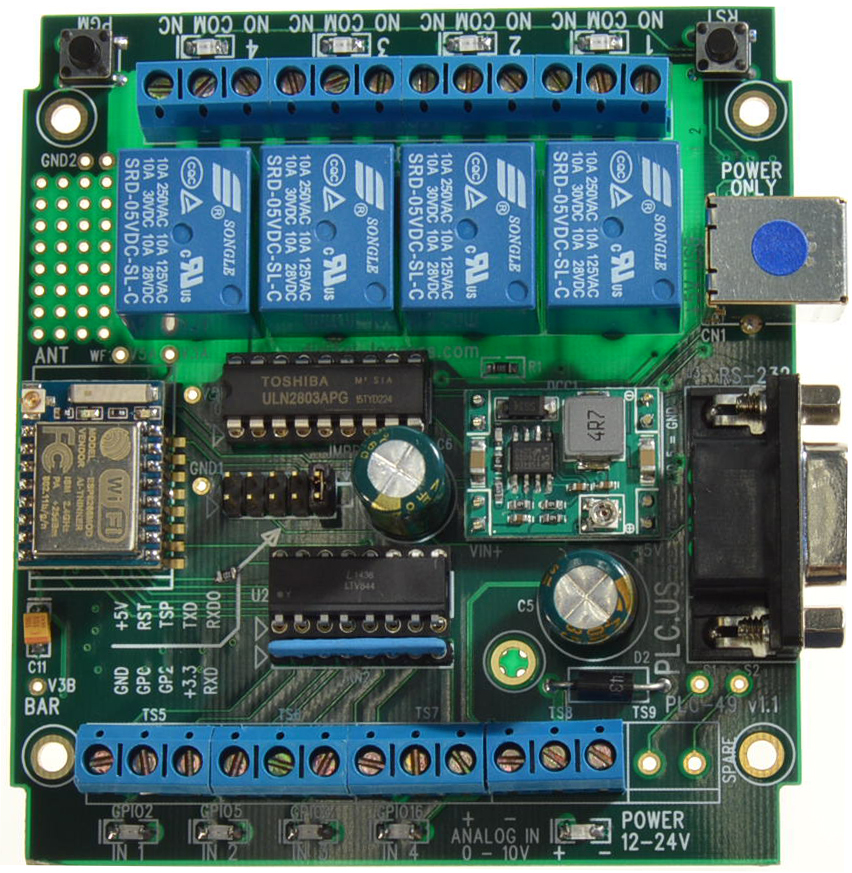
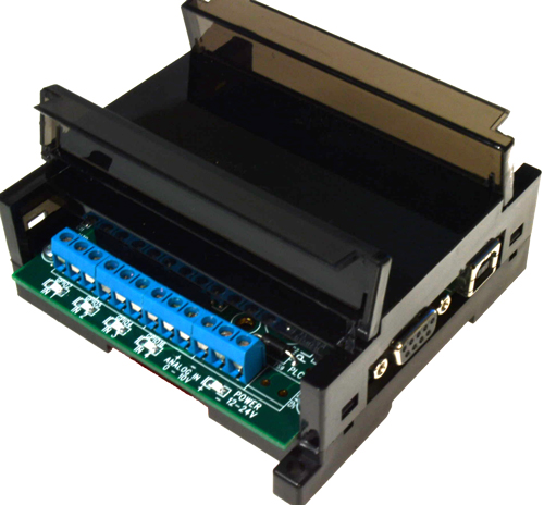
The PLC is built on a single 4-layer PCB with a plug-in WiFi Module. The top of the board contains the terminals, LEDs, switching power supply, opto-isolator, relay driver, relays and I/O jacks. There is also a hardware hacking area with a .1" hole grid in the upper left corner. There are two switches, RST (reset) and PGM (enter program mode). The bottom of the board contains fuses, input protection, a 3.3V regulator, an RS232 level converter and a prototype area for an SO8 IC.
Powering the PLC
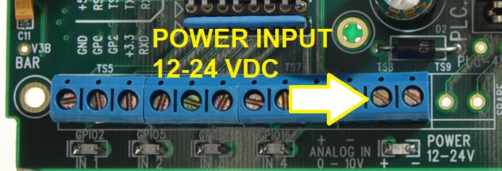
The PLC is designed to run from 12 to 24 volts DC at 200-100mA, via the two power input terminals TS8 above. The power input is protected against reversed polarity by D1. Input power voltage transients over 30V are clamped to ground by a TVS diode D2. A bucking switching regulator module takes the input voltage less about 0.4V diode drop down to 5VDC for driving the relays and powering a secondary linear regulator. A decent amount of bulk capacitance is provided to filter out power-glitches, relay transients and WiFi current surges. The 3.3V ESP8266 Wifi module is powered from a secondary regulator U4. If 12-24V power is not desirable, the PLC may be powered from a 5V supply by connecting the USB cable to a powered device or a wall adapter. When properly powered, the blue LED illuminates without flickering.
Inputs
There are 4 digital and 1 analog inputs:
Digital Inputs
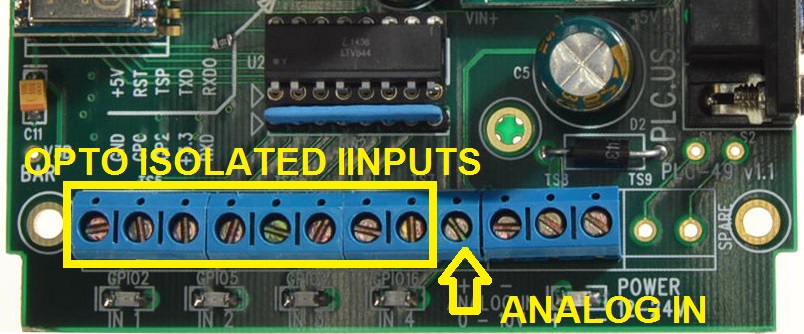
The digital inputs are located on the bottom left screw terminals. Digital inputs are isolated from the outside world by opto-couplers. The opto-couplers have bi-directional LEDs which will respond to inputs of either polarity and may be used for AC or DC detection. There are 6K Ohms of resistance in series with the LED's. Recommend input input voltage is from 3 volts to 24 volts. External resistors can be added to increase the input voltage limits. For example, adding an external 6K series resistor would change the input range to 6-48V. Consider V^2/R power dissipation in external series resistors when using high voltage inputs. You can replace the supplied SIP resistor pack with a different value to change the input sensitivity. The 6K resistor pack supplied will operate from 5 to 24V. The spare yellow resistor pack can be substituted for lower voltages, ie. 3.3 to 5V. When changing the series resistor, input current must be kept below 20 mA to avoid damaging the opto-coupler LEDs. The opto-coupler outputs are connected to GPIO pins on the 8377 module. These slew rate of these input pins can be changed by enabling or disabling internal pull-up resistors. Each input is fully isolated and will sense either positive or negative voltage. One side of the input can be either connected to an AC or DC voltage source, or it may be connected to ground. Supplying a positive power to one pin creates active-low inputs. Grounding the pin creates active-high inputs. You can safely use the opto-isolators as AC voltage sensors by putting a small capacitor, ie 0.1uF in series with the line voltage. The opto-couplers provide at least 2500V input protection. An LED illuminates when each input is active.
Analog Input
There is a single ADC input channel with approximately 10 bit resolution over 0-10V. There may be some compression at the top of the ADC scale, so it is recommended that you leave at least 10% headroom in your design.
There is a voltage divider made up of R18 and R21. The WiFi module's input range is a nominal 0 to 1 volt. Input impedance is about 100K Ohms determined by the voltage divider resistors used.
The ADC shares a common ground with the power supply negative terminal. This input is protected against over-voltage by a series resistor and zener diode D4. You may increase or decrease the value of the series scaling resistor to change the input range.
Outputs
There are four relay outputs.
Relays
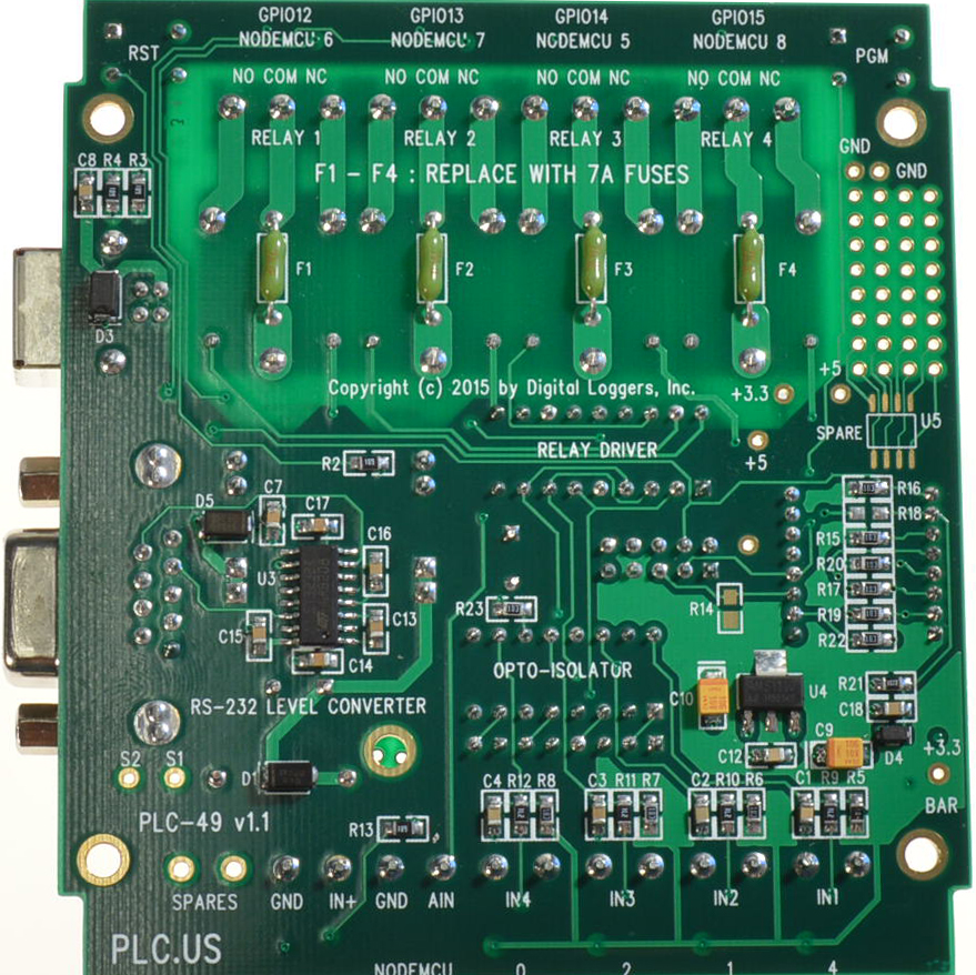
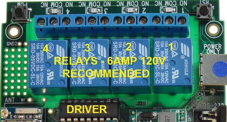
The relays are located on the top of the PLC. While they are rated at 10A, we have found they have much longer life at 6A, and recommend that as a maximum current. The four relays are driven from the microcontroller through ULN2803 U1 which also provides inductive kickback protection. Kickback can be generated by the relay coils themselves or by external loads. Each relay is an SPDT type protected by a 7 Amp fuse. The fuses are mounted on the bottom of the circuit board and are soldered in place. A spare fuse which looks like a small green resistor is supplied just in case. Be careful not to exceed 8 Amps or fuse replacement will be necessary. Each relay has it's common, normally open, and normally closed terminal brought out to a terminal strip. The normally closed terminal can be used for loads that need to be on when the PLC is powered off. The relays can easily handle DC or DC loads, up to 120 VAC or 24VDC at 6 Amps. We suggest that the relays be driven at 100% (on continuously), without PWM. Although it's tough to damage, the ULN2803 driver is in a socketed DIP package for easy replacement. LEDs above the relays illuminate when the relay is powered, ie NO contacts have closed, and NC contacts have opened.
RS232 Serial Port
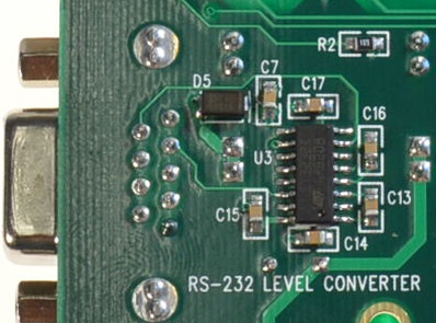
There is a two wire, RS232 serial port available on J3, a PC compatible DB-9 serial port. It can connect straight-through to a PC serial port or to an RS232 to USB converter. The range of the RS232 port depends on baud rate, cable quality and interference, but it will go a long way, typically 1000+ feet. Note, in this design, the RS232 port carries the data. The USB connector is a power input only. So if you'd like to program or control the PLC, use the RS232 connector, not USB. This architecture allows you to "tether" the PLC on a serial port, possibly using the AT Firmware or NodeMCU On the DB-9, Pin 3 is RXD, the data into the ESP8266, pin 5 is ground and terminal 2 is TXD, the data transmitted out of the microcontroller. Handshaking lines are tied together. The levels are RS232 (+/- 5 to 12 volts) not TTL. Avoid connecting the RS232 output to a TTL device. It will likely damage it. ESP8266 serial port 1 is used. The SP202 RS232 translator chip converts TTL to RS232. If you have a requirement for TTL levels, it's possible to convert tap the ESP8266 3.3V TTL data pin by removing the jumper on pins 9 & 10 of the expansion header. Note, this removes the input protection on the serial input bit, so be cautious if you make this modification. Driving it with 5V might damage the 8266. If you install the "hardware hacker" expansion board, you can loop the serial data line through another IC, a small microcontroller for example. If you remove the jumper and don't need to use the serial data stream, just add a small jumper wire on the expansion board.
ESP8266 Firmware
The control processor and WiFi radio are combined inside the popular ESP8266 WiFi chip. This implementation is actually an ESP-07 module with expanded memory. It is powered from it's own 3.3 volt regulator U4. There is an internal antenna and a U.FL connector for an external antenna to increase WiFi range. The ESP8266's firmware can be upgraded by pressing SW2, labeled "PGM" on the PCB, then pressing
and releasing SW1, labeled "RST". Note that some programming utilities requre that the PGM key be pressed and held until data transfer begins. New code is sent over the RS232 serial connection.As provided, the ESP8266 is programmed with NODEMCU. It can be used as-is or reprogrammed with one of the many custom microcodes found on the Web. A number of public-domain tools and firmware options are available for the ESP8266. Popular platforms include the factory AT firmware, NodeMCU (includes a wonderful Lua interpreter), and Frankenstein. The popular Arduino IDE is now available as well. ESPLORER is a nice tool for experimenting with firmware options. Firmware support is best obtained via the online communities - Digital Loggers isn't able to provide ESP8266 support directly, but we are happy to answer any hardware questions. We suggest re-flashing the ESP8266 using the connector on the board until your code is stable and proven. Also, we'd recommend you don't use Init.lua until your code is fully debugged. When you do switch over to init.lua, leave some power-on code to exit the process in case an error occurs. This will save you some time by not having to reflash the entire module if you make a mistake.
Programming / Expansion header
J4, internal to the unit, is a programming header for the ESP8266 that can also be used to add extra functions to the unit. It has the 3.3 volt level serial prot signals, GPIO0, GPIO2, Reset, power/ground, and a signal which connects to the RS232 level converters second transmit input (signal TSPARE). In normal operation, there's a jumper installed between pins 9 and 10 of this header, connecting the RS232's receive output to the ESP8266. One use of this connector would be to add a small microcontroller to control the ESP8266. By removing the jumper and connecting an external 3.3 volt level serial connection, you can have control of the ESP8266. A small microcontroller could then interface to many different sensors to expand the PLC's I/O or to interface to special modules not supported though the usual I/O on the PLC. J4 pinout:
1 = ground
2 = VCC (5 volts, but note the signals are 3.3 volt levels)
3 = GPIO0 (connected to ESP8266 and PGM switch, used to enter ESP8266 boot mode)
4 = Reset (connected to the ESP8266 and reset switch)
5 = GPIO2 (driven from PLC input 1 from optoisolator)
6 = TSPARE (connected to the RS232 level converter's second transmit channel)
7 = 3.3 Volts
8 = TXD (3.3 volt level output from ESP8266)
9 = RXD (3.3 volt level input to ESP8266
10 = RXDO (3.3 volt level output from RS232 receiver, normally jumpered to RXD)
A plugŁin expansion breadboard connecting to J4 is available as a option which fits over the capacitors C5 and C6 and into J4. There's a smaller prototyping area in the upper left of the PLC board itself.
Wiring Example
Here's a Fritzing example:
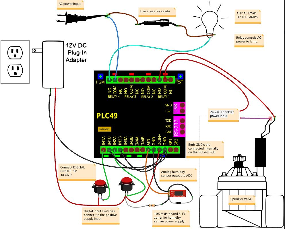
Here is a Fritzing example of how to wire up the various I/O's. It shows how
to use the relays to control an AC lamp and a sprinkler valve. A 12 volt at 1
Amp adapter is used to power the PLC. Connect it's positive output to the +
input and it's negative output to the Ł input. The lamp is controlled by relay
4. An AC cord is used as the power to the lamp. It's a good idea to insert a
fuse in the AC line to protect the relay and it's internal fuse, which is
soldered onto the bottom of the PLC's circuit board. The internal fuse is 7
Amps so use something smaller, 5 Amps or less is a good idea. Connect the line
(hot)
side of the AC cord to the fuse and the neutral side to the COM4 terminal on the
PLC. The NO4 terminal connects to one side of the lamp and the other side of
the lamp connects back to the fuse. When Relay 4 is command ON, then the lamp
will light. NO stands for "normally open" and NC stands for "normally closed".
They are the states of the relay contacts when the relay is not energized.
A sprinkler valve is controlled the same way. They do not use AC line voltage
to operate, but instead, most use 24 Volts AC from a step down transformer. A
valve is shown connected to Relay 1.
Two push button switches are shown connected to the digital inputs (1 and 2).
The digital inputs are isolated by a biŁdirectional optocoupler. They can be
driven by signals that have no relationship to the PLC's ground connection.
Here, we connect one input to ground and another to a switch to the positive
power input. When the switch is pressed the input voltage will be applied to the optocoupler channel and it's output can be read by software. The digital inputs
can go as low as 3 volts so can be used to detect 3.3 volt logic signals, or as
high as 24 volts to detect external motor's, PV solar, or other higher voltage
sources.
The analog input is setup to measure 0 to 10 Volt signals. It's protected
against high voltage and reversed polarity signals. The Fritzing shows a
Sparkfun analog output humidity sensor https://www.sparkfun.com/products/9569
connected to the analog input. The humidity sensor needs about 5 volts for it's
power supply. We generate that with a simple 5.1 Volt Zener diode regulator from
the PLC's input power supply. A 10K resistor should be fine for this
application as the sensor uses less than 250uA. The humidity sensor can be read
by software to prevent watering the lawn while it's raining outside.
Incredible Value - Just $49!
The price is right. Try yours risk-free for 15 days. Call (408) 330-5599 for expedited shipping, and international orders.