IoT Relay II FAQs

Q: How do I connect to the trigger input?
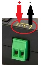
A: Remove the green Phoenix connector by pulling gently. It slides
out horizontally. Use the
screw terminals to attach two wires. Negative or (-) to GROUND and
positive (+) to the trigger voltage, ie a logic level GPIO pin. Since the relay includes a debounce circuit, AC can also be used as a trigger. See video examples below.
Q: Is the trigger input polarized?
A: The relay will trigger from AC or DC. DC polarity is labeled above the connector:
Q: How much current does it take to trigger the control port?
A: About 0.2mA, the input is constant current. 12-120VAC or 3.3-48VDC will trigger the relay. DC trigger input is polarity sensitive. Pay attention to the positive(+) and negative(-) markings above the trigger connector.
Q: What's new in version II?
A: We changed the outlet configuration to offer two Normally OFF, one Normally ON, and one Always ON - per customer request. We improved the isolation voltage and gapping, used higher voltage hi-pot testing, added a mounting tab and improved AC trigger operation.
There's only one large relay inside, so you can't control the 4 outlets separately.
Q&A: Do you have a print? More detailed specifications?
Q: How much power can it handle?
A: 12A at 120V is 1440W, or 1.44kW. Check the spec sheet here.
Q: How much power does it draw when switched on?
A: -- AC Side When energized, the relay itself draws about 1.2 watts, or 0.010Amp at 120VAC. The total AC current draw is the sum of the relay current and your attached load, so if you had a 12Amp load for example, the input current measured at the AC cord would be 12.01A.
So the relay itself is a low power device for switching high power loads.
--DC Side The input trigger current to the optoisolator is about 2-3mA at 5V, or 0.002Amp at 5V so you can connect it directly to 5V or 3.3V TTL logic.
The current drawn by the trigger input does not depend much on input voltage (unlike a normal relay). That's because there's a trigger circuit inside, so the same terminals can run on a 3.3V or on a 48V DC trigger voltage and the relay will behave identically.
Q: Does it come with a power cord?
A: It includes a short (about 2' long) detachable 14AWG UL grounded power cord, type C-13 to 5-15.
Q: What's on the inside? How does it work?
A: Ladyada opens it up, tells you what's inside and how it works.
Q&A: What's a relay anyway? How can I connect one? Relay basics, please...
RPi Example
A series for students using the IoT relay including videos.
https://github.com/prichardsondev/RaspberryPiServer
Arduino Example
A microcontroller is a perfect mate for the IoT relay.
Here's how they connect:
This code is just like the Arduino BLINK example. There are three parts: 1. Specify the pin, 2. Initialize as output, 3. Toggle a data bit to control the relay.
int relay = 13;
// Tells Arduino the relay is connected to pin 13
void setup()
{
pinMode(relay, OUTPUT); // Initialize the Atmel
GPIO
pin as an output
}
void loop()
// Loops forever
{
digitalWrite(relay, HIGH); // Turn the relay on (HIGH is the voltage
level = 1)
delay(5000);
// Stay ON for 5 seconds
digitalWrite(relay, LOW); // Turn the relay off by making the
voltage LOW = 0
delay(5000);
// Stay OFF for 5 seconds
}
GPIOs on
PIC chips, Raspberry Pi, Intel Gallieo, Edison and others are very similar.
It's just too easy :)
PC USB Power Connection Example
Here's a very simple example showing how "sniffing" the power from a USB
port can be used to trigger a relay. No programming is required. The relay will
activate when USB power is present, and de-activate when USB power is
turned off. Turning the relay OFF (no power) sets the normally ON outlets
ON and normally OFF outlets OFF. Powering up the relay via the control
input inverts this.
You can disable USB power with a command like this:
devcon.exe disable @USB\*
or by setting
KEY_LOCAL_MACHINE\SYSTEM\CurrentControlSet\Services\USBSTOR
= 4
Parallel Port Example
Let's say you'd like to connect a number of IoT relays to a parallel
port. Here's a video showing how:
The computer side of a parallel port is a 25 pin D-shaped female connector. The
mating connector is called a "male DB-25". Low cost USB->Parallel adapters do
the job.
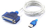
Printers and other devices (such as the IoT relay) can be wired
directly. The 8 output pins are listed below:
| Pin | Function | Hex Value |
| 2 | D0 | 01 |
| 3 | D1 | 02 |
| 4 | D2 | 04 |
| 5 | D3 | 08 |
| 6 | D4 | 10 |
| 7 | D5 | 20 |
| 8 | D6 | 40 |
| 9 | D7 | 80 |
Pins 18,19,20,21,22,23,24 and 25 are all ground pins. Grounds connect to the
negative pins on the relay.
In the video, we connected the positive wires to the data pins 2 and 3, and the
negative wires to pin 24 and 24.
When the port outputs a zero on but 1, ie 0x00, the relay is off. When the port
outputs a 1 bit, ie 0x01, the first relay turns on. When the port outputs a 2
bit, 0x02, the
second relay goes on. To turn both relays on, output a 3. You can see how this
extends easily to 8 relays.
Communicating with the port is easy. If the port is on the motherboard,
you can directly write to an I/O port. If you're using a USB to Parallel adapter,
you'll need to
"bit bang"
through the driver. Here's an example of direct control from
older versions of Windows:
void main (void)
{
outportb(0x378,0xff); /* turn all relays on - 0x378 is the IO address AKA LPT1*/
getch(); /* wait for keypress before switching off */
outportb(0x378,0x0); /* turn all relays off*/
}
Newer versions of Windows restrict direct access to I/O ports for security.
But
you can
still "bit bang" most of them.
A library function can simplify things:
parallel.setData(0) # sets all pins low (all relays off)
parallel.setData(255) # sets all pins high (all relays on)
PC USB -> Serial Port Example
It's easy to use a USB to serial adapter with a couple IoT relays.
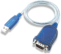
Just connect the handshaking lines and a ground pin:
| DB-9 Pin | Function | DB-25 Pin |
| 4 | DTR (wire this pin to the IoT relay #1 + pin) | 20 |
| 7 | RTS (wire this pin to the IoT relay #2 + pin) | 4 |
| 5 | GND (wire to both relay - pins) | 7 |
| 3 | DATA OUT (another relay can go here*) | 2 |
If you have an FTDI based adapter, there's a nice internal bit-bang mode. There several ways of controlling these bits from Windows, including the EscapeCommFunction Here's the Linux serial "howto". This is often easier than using a USB-> parallel adapter, but there is a limitation: There are only 2 or 3 bits, so you can use at most 2-3 relays per adapter. *The third relay on the TX data will work only if you can send a persistent "break" from your environment..
Linux
Direct I/O Example
Here's the code to directly control a parallel port in Linux:

#define port 0x378 /* For "LPT1", the printer port base address is 0x378 */
#define Both_ON 5 /* This is the numeric value to send to printer port, for example
5 (4+1) turns D0 and D2 on */
outb(port, Both_ON); /* Turns both relays 1 and 4 on */
delay (1000);
outb(port, 0); /* Turns all relays off */
Here's a command line
example.
Using the Relay Without a Micro
Thanks to the universal input, it's easy to use the relay without a
microprocessor. You can use most any AC or DC signal to turn things on (or
off) at the same time.
Here are a few examples from real customers:
Alarm System - Flashes 120VAC lights when alarm is activated:
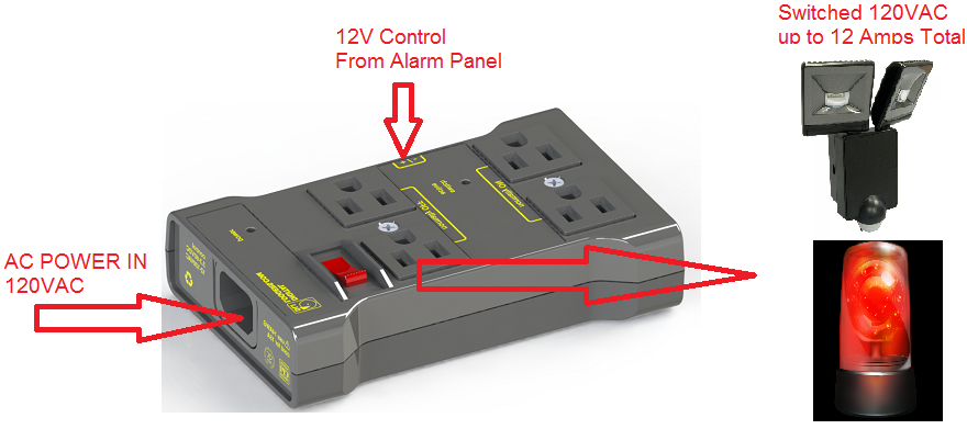
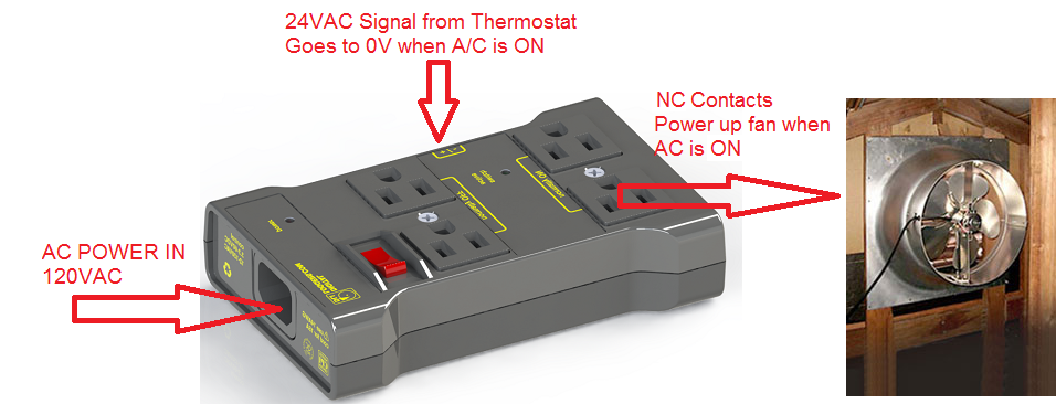
Attic Fan Control Control - Turns attic fan circuit on when air-conditioner is running:
Turn on worklights and stereo on, turn off shop-vac when power-saw is active:

If we haven't answered your questions here, please call (408) 330-5599 or send us an email. We'll be glad to help.
© Digital Loggers, Inc. 2005-2022.