Frequently Asked Questions
Last Updated 09/06/2016ETHERNET POWER CONTROLLER III
Download a users guide. Check the specifications.
Learn about the NEW model here - or call (408) 330-5599 for a free trial
How do I set up network access from an Apple Macintosh? - Thanks to John McClintock for these instructions
How do I set up Internet access? -Thanks to Mike G. for these detailed instructions.
How do I enable AutoPing?
How do I enable Battery Backup?
How long will the battery run?
What is the battery lifetime?
What's the new BASIC Scripting Language all about?
What's syslog? How can I keep an event log?
What is the LCD for?
How can I control that neat LCD display?
What is the current version of firmware?
How do I update the firmware?
What is the default IP address? How do I reset to defaults? What is the default password?
On initial setup, I can't establish a Ethernet communications from a Windows PC. Help!
How can I control the switch from my own applications?
Can you develop custom firmware for my application?
Can you develop custom hardware for my application?
Do you have PowerMan support?
Can you explain the auto-ping settings?
What are the CRITICAL and PROTECT functions?
Do you have a C++ programming example?
Do you have a .NET programming example?
Do you have a Java programming example?
Do you have a compiled Windows command line
tool or a Perl example?
Do you have a Python programming example?
Do you have a Crestron control module?
Where can I find iPhone, iPad, or Android apps for Digital Loggers?
How can I use the serial port?
| Question: | What is the current version of firmware? |
| Answer: | The current version is on the update page Find the revision history here, and firmware update instructions here. |
| Question: | I have on earlier Ethernet Power Controlller II or PC-8000 model. Where can I find information? |
| Answer: | For firmware information on PC-8000 units without power metering, (circa 2008-9), click here. For information on the Ethernet Power Controller II or Ethernet Power Controller II LCD (circa 2010 to 2011), click here. |
| Question: | How can I control and customize the LCD display? |
| Answer: | The LCD can be used to display current and voltage settings, outlet status, or any message of your choice. You can operate the LCD in "billboard" style, displaying a series of user defined messages. To customize the LCD, you'll want to write a script using our BASIC scripting language. You can also use the display to send messages from remote systems (ie. service alert warnings). To send messages remotely, write a script first, saving it in EEPROM then start the script from your remote system. Learn more about scripting here. |
| Question: | On initial setup, I can't establish a Ethernet communications from a Windows PC. Help! |
| Answer: |
If your default Windows settings won’t access the controller, use a crossover cable and follow
these steps to reach the controller’s IP. You'll find a
more extensive
explanation
in the user's manual.
|
| Question: | How can I control the switch from my own applications? |
| Answer: |
Downloadthe latest User Utility
which includes PowerMan support for Linux. Your application can use HTTP communications.
Here are Java, .NET, Perl and C++ examples with source.
Windows users can download a Perl interpreter to run the script version. This script (ver 4.x) is compatible with all DLI power controllers. |
| Question: | Do you support PowerMan? |
| Answer: | Yes, absolutely. The latest code is added to the tarball. Download the latest User Utility here. |
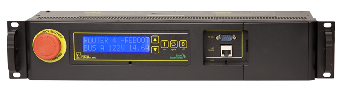
| Question: | What is the blue LCD for? |
| Answer: | The blue LCD shows outlet status during power up, the IP address, netmask, outlet names, and other useful information. Time and date stamps for significant events (such as power outages or emergency shutdowns) are also displayed. You can program this display to display your own messages using the scripting feature. |
Back To Top

If we haven't answered your questions here, please call (408) 330-5599 or send us an email.
We'll be glad to help.
© Digital Loggers, Inc. 2005.