Digital Loggers

Frequently Asked Questions for -48 Power Switches
Last Updated 01/13/2014.
 

Download the users guide.  

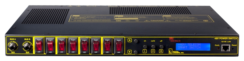
Questions?  Like to order? Call now - (408) 330-5599

Frequently Asked Questions


How do I set up network access from Windows?
How do I set up network access from an Apple Macintosh? - Thanks to John McClintock
How do I set up Internet access from a home router? -Thanks to Mike G.
How do I enable AutoPing?
What's syslog?  How can I keep an event log?
What's the Scripting Language all about?
How can I communicate with the unit using HTTP commands?
What are the contact ratings?
How are the A & B busses connected?  Are the returns tied?
What is the power dissipation?  
What are the power requirements?

What are the mounting dimensions?
What is the physical size?
What is the current firmware version?
What is the default IP address
How do I reset to defaults
What is the default password?
On initial setup, I can't establish a Ethernet communications from a Windows PC.  Help!
Do I need a crossover cable?
How can I control the -48 switch from my own applications? 
 How can I send HTTP requests?
Can you develop custom firmware for my application?
Can you develop custom hardware for my application?
Do you support PowerMan?
Can you explain the auto-ping settings?

What are the CRITICAL and PROTECT functions?
Do you have a Visual Basic.NET example program?  Thanks to Alan Holmes
Do you have a Python programming example?
Do you have a C++ programming example?
Do you have a .NET programming example?
Do you have a Java programming example?
Do you have a compiled Windows command line tool or a Perl example?
Where can I find iPhone, iPad, or Android apps for Digital Loggers?


Question:        What are the contact ratings?

Answer:           All eight internal T-90 Relays are rated at 20A DC. Contacts are MOV protected.

 Relays are RU and CE approved, and rated at 250,000 operations MTBF at 50% load.  Case terminals are rated at 25A  Breakers are rated at 15A.  Only stranded wire of appropriate gauge should be used.  Terminals must be well torqued.  It is wise to recheck torque after completing the installation.  Heavy traces and gold plating are used to minimize internal resistance between the terminals and relay contacts, typically 25m Ohms, so internal contact power dissipation is not normally a consideration. For maximum flexibility, relay contacts are unprotected.  An internal MOV is provided for arc protection to extend contact life.


Question:        How are the A&B busses connected?

Answer:           The first four relays connect to "BUS A".  Relays 5-8 connect to "BUS B".  The web server is powered from either bus.  The return connections are bonded internally.  Each bus and branch circuit includes a separate breaker.


Question:        What are the power requirements?

Answer:           The controller dissipates a maximum of 10.48W at 48VDC  input with all relays on.   Power dissipation decreases with input voltage due to the use of an efficient switching power supply. Typical dissipation with relays off is 3.1W.  Although the case is well ventilated, ambient air temperature should not exceed 140ºF for maximum reliability.   The internal power supply is redundant and diode isolated.  It is powered by either the A or B bus.


Question:        What are the mounting dimensions and physical size?

Answer:           RETMA 1-U form factor, 13" mounting depth including allowance for cables.  Height 1.750", width 17.00", ear-to-ear width 19.00 


Question:        What is the current version of firmware?

Answer:           The current version is  on the update page  Find the revision history here, and firmware update instructions here.


Question:     What is the default IP address?  How do I reset to defaults?  What is the default password?

Answer:         If you have lost the IP address or admin password or selected DHCP when it is not available, follow this procedure to reset to the default IP address of 192.168.0.100:

  • Press and hold the reset button for 5 seconds to reset the network settings, user name and passwords.  The reset button is accessable through a hole located underneath the unit.  Gently press it with a pencil or small tool.

The default master login is "admin" and default password is "1234".  This procedure resets the admin login and IP address and lockout, but doesn't affect outlet names and links.


Question:     On initial setup, I can't establish a Ethernet communications from a Windows PC.  Help!

Answer:       If your default Windows settings won’t access the controller, use a crossover cable and follow these steps to reach the controller’s IP. 

METHOD 1

  • Before adding an IP, close network programs and browsers.
  • Go to the Network Settings – Local Area Network or use the keyboard shortcut <Windows-R> - type “ncpa.cpl” and click OK. 
  • Right click on your LAN connection and choose “Properties”
  • Highlight “Internet Protocol” and click the “Properties” button.
  • Make note of the current settings.
  • Select "Use the following IP address".
  • Enter an IP address such as 192.168.0.5.
  • Enter a subnet mask of 255.255.255.0.
  • Delete any gateway entry.
  • Close all windows for the configuration to take effect.
  • Start your Browser and type 192.168.0.100 in the URL field. The index page should be displayed.
  • The default user name is "admin" (lower case) and password is “1234”
  • Set the IP address of the unit to your network, then restore your settings.

METHOD 2

  • Before adding an IP, close network programs and browsers.
  • Go to the Network Settings – Local Area Network or use the keyboard shortcut <Windows-R> - type “ncpa.cpl” and click OK. 
  • Right click on your LAN connection and choose “Properties”.
  • Highlight “Internet Protocol” and click the “Properties” button.
  • Click the “Advanced” button.
  • Under the IP Address settings, click the “Add” button.
  • Enter a new IP, such as 192.198.0.5, and a subnet mask of 255.255.255.0. Press the “Add” button.  This new IP is added the list.
  • Close all windows for the configuration to take effect.
  • Start your Browser and type 192.168.0.100 in the URL field. The index page should be displayed.
  • The default user name is "admin" (lower case) and password is “1234”.
  • After configuring the unit, you may delete the additional IP address.


Question:     Can you explain the auto-ping settings?

Answer: 

  • Enabling auto-ping

  • To enable auto-ping, the check-box to the left of the IP address must be checked, then the change button pushed. You will get a message "Autoping will automatically be enabled after 10 successful pings". This prevents rebooting units before conditions are properly established.


  • Time Between Pings
    The time between which each ping is set. The time between pings to a particular device is (Time_Between_Pings * Number_of_devices_enabled_in_the_ping_list).


  • Ping failures before reboot
    Number of times the ping has to fail (in a row) on a given device before it is power cycled.


  • Times to attempt reboot
    Number of times to attempt power cycling before giving up and disabling auto-ping.


  • Device reboot delay
  • Length of time after a power cycle before checking for a response from the device. This allows a device or computer time to completely boot up.


    Question:        How can I control the switch from my own applications? 

    Answer:            Download the latest User Utility. Your application can use HTTP communications. There is also a C++ example with source (4/11/06 - 483k). This program displays the controller name, switch names and switch status via HTTP. You can also toggle the switches on and off.  Also included is PowerMan support for Linux.

    Windows users can download a Perl interpreter to run the script version.  This script (ver 4.0) is compatible with all DLI power controllers.


    Question:        Can you develop custom firmware for my application?

    Answer:         Gladly.  We've done this for many customers.  Our programming rate is $75/hour.  After we agree on a -very specific- project description, we can send you an estimate of the time involved to code, debug and test.   


    Question:        Can you develop custom hardware for my application?

    Answer:           Gladly.  We've done this for many customers.   Please call with your requirements


    Question:        Do you support PowerMan?

    Answer:           Yes, absolutely.  The latest code is added to the tarball.  Download the latest User Utility here.


    Back To Top


    If we haven't answered your questions here, please call (408) 330-5599 or send us an email.  We'll be glad to help.

    © Digital Loggers, Inc. 2005.