Frequently Asked Questions for DIN Relays12/02/2024 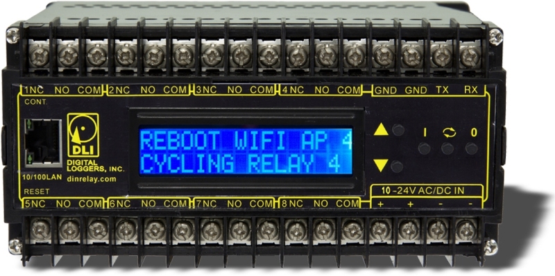 Download the online manual. Download a printable manual. Check the spec sheet. This product is superseded by the latest DIN relay. Call (408) 330-5599 How can I control
higher-current loads? Question: What's new in this product? Answer: In our second version, DIN Relay II, with serial numbers DIN22000 and higher, we added these features:
In version 3.0 of DIN Relay III, we added these features:
In version 3.1, we added these features:
Tell us what you'd like to see in the next version - engineering@digital-loggers.com Question: What are the contact ratings? Answer: All eight internal T-90 Relays have the following ratings:
Relays are RU and CE component approved, and rated at 250,000 operations MTBF at 50% load. Case terminals are rated at 8-12A, depending on agency. Only stranded wire of appropriate gauge should be used. Terminals must be well torqued, but not over 10in/lbs. It is wise to recheck torque after completing the installation. Heavy traces and gold plating are used to minimize internal resistance between the terminals and relay contacts, typically 25m Ohms, so internal contact power dissipation is not normally a consideration. For maximum flexibility, relay contacts are unprotected. For high current inductive switching, consider adding an external snubber circuit to extend contact life. Download contact protection information from https://www.digital-loggers.com/relaycare.pdf Question: What are the power requirements? Answer: The relay dissipates an absolute maximum of 5W during switching with all relays on. Power dissipation decreases with input voltage due to the use of an efficient switching power supply. Typical dissipation with relays off is 2W. Although the case is well ventilated, ambient air temperature should not exceed 135şF for maximum reliability. Surges over 40V P-P may damage the internal regulator. The relay will shut down at input voltages below 9VDC. If you expect to encounter brown-out conditions in your application, set the Power-on-Recovery Mode on the setup page for safest operation. To prevent oscillation, a brown-out re-latch function is also provided on the Setup page in firmware versions 1.6.9 and later. In the event of a brown-out, you may specify a time period after which the relay will attempt to re-latch the contacts. This function is disabled by default and has no effect if the relay is properly powered. Please read the UVLO and OVP suggestions below. Add an external MOV or other protection device across the power input terminals in noisy environments. Power consumption below does not include any load on the +5V accessory output. We are working hard to make this the most efficient product in its class.
The +5 output is protected by an auto-resetting polyfuse PPTC. Overloading this output will thermally shut down the polyfuse. Remove the load and allow 60 seconds for the fuse to reset if this occurs. Question: Can I invert AutoPing or the Web Page to use NC contacts? Answer: For safety reasons and to prevent support issues, we have not implemented an "invert relay" function in either the web UI or AutoPing. You can drive the relays in reverse by:
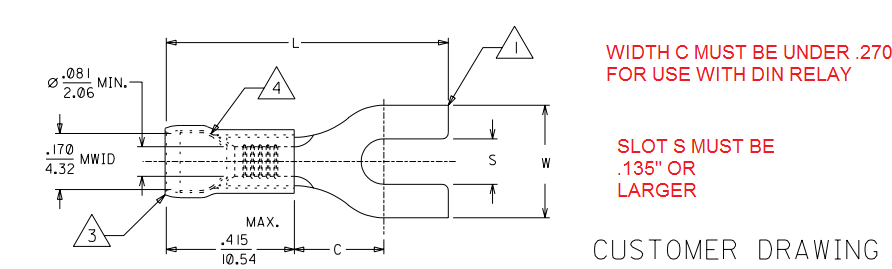
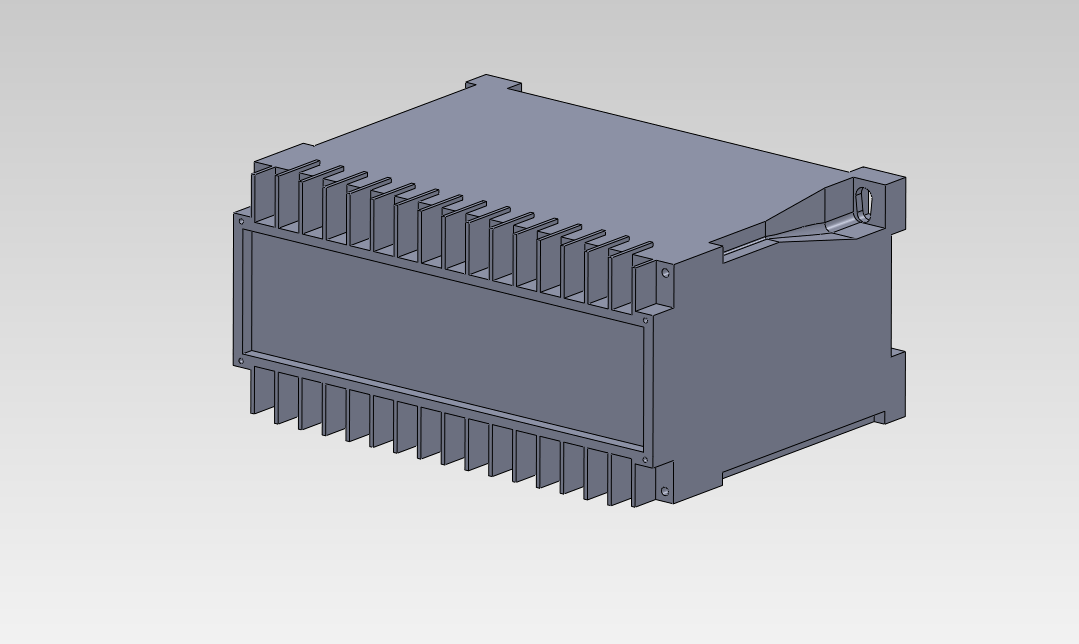
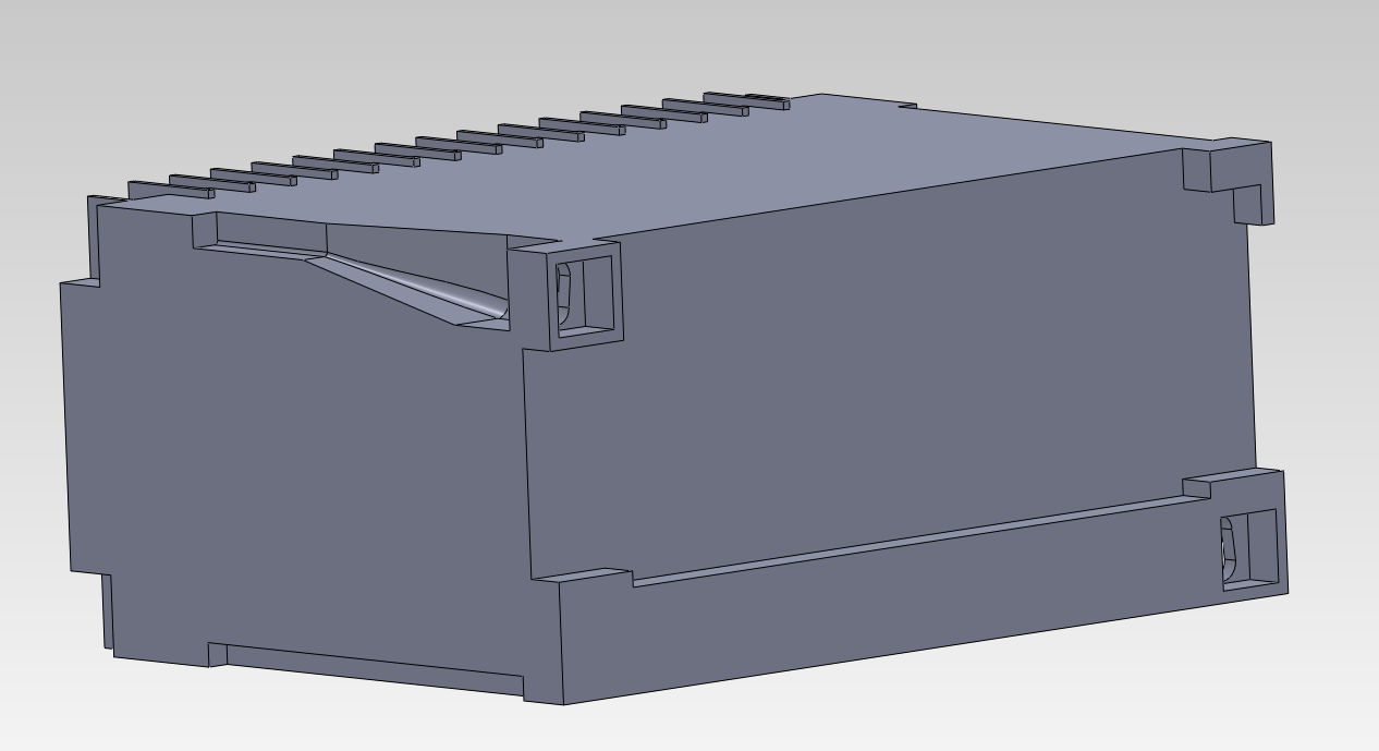
You can also use the programmable web links to start a script. For example, a link like "CIRCUIT 1 OFF", could be lined to a script 2. ON 1, 3. END. This inverts the "OFF" operation by closing the relay. Question: What are the mounting dimensions and physical size? Do you have drawings? Answer: Mounting holes are located on 5.308 x 1.968” centers. Download a 2-D print here (.pdf). Find a 3D SolidWorks drawing file here and a SolidWorks part-file here. Here are BMP graphics of the front and back of the relay. Question: What terminals should I use? Answer: Any fork or "spade tongue" terminal with a width of .270 or less and a slot of .135 or larger will work fine. Size the barrel to terminal to match your wire gauge. Be careful not to over-torque.
What is the current version of firmware? Answer: The current version is on the update page Find the revision history here, and firmware update instructions here. What components do I need to build a remotely powered DC site using the DIN relay as a power controller? Answer: In addition to the load (ie. APCam, PtP link, AP, etc), you'll need a battery, some source of power, ie wind or solar, and most importantly a charge controller with OVP and UVLO features. Over Voltage Protection is needed for reasonable battery life. Under Voltage Lockout is needed to correctly reset attached devices as well as the DIN relay and to prevent oscillation when the battery is nearly discharged. Question: What is the default IP address? How do I reset to defaults? What is the default password? Answer: If you have lost the IP address or admin password, follow this procedure to reset to the default IP address of 192.168.0.100:
The default master login is "admin" and default password is "1234". This procedure resets the admin login and IP address and lockout, but doesn't affect outlet names and links. Question: Wiring and terminal information? Answer: Use stranded wire from 28AWG to 14AWG, or crimp and use .187-.250 spade lugs. Ring terminals and solid (unstranded) wire should not be used. Maximum torque recommended by the terminal manufacturer is 10in/lbs. Excessive torque will tear the terminal from the internal PCB, cracking the solder joint and could potentially cause safety issues. Question: On initial setup, I can't establish a Ethernet communications from a Windows PC. Help! Answer: Follow
the instructions in this
document.
Question: Can you explain the auto-ping settings? Answer: To enable auto-ping, the check-box to the left of the IP address must be checked, then the change button pushed. You will get a message "Autoping will automatically be enabled after 10 successful pings". This prevents rebooting units before conditions are properly established. The time between which each ping is set. The time between pings to a particular device is (Time_Between_Pings * Number_of_devices_enabled_in_the_ping_list). Number of times the ping has to fail (in a row) on a given device before it is power cycled. How many pings should be sucessful before enabling the autoping. This setting prevents enabling autoping on an unreliable network and rebooting equipment unnecessarily. Number of times to attempt power cycling before giving up and disabling auto-ping. Find a more detailed description of Auto-Ping here. Find instructions on modifying Auto-Ping behavior using scripting here. Question: How can I control the switch from my own applications? Answer: Download
the latest User Utility which includes PowerMan support for
Linux. Your application can use HTTP communications.
Here are some examples
with source. Question: Can you develop custom firmware for my application? Answer: Gladly. We've done this for many customers. Our programming rate is $75/hour. After we agree on a -very specific- project description, we can send you an estimate of the time involved to code, debug and test. | ||||||||||||||||||||||||||||||||||||||||||||||||||||||||||||||||||||||||||||||||||||||||||||||||
|
Question: Can you develop custom hardware for my application? Answer: Gladly. We've done this for many customers. Please call with your requirements Question: Do you support PowerMan? Answer: Yes, absolutely. The latest code is here: Download the latest User Utility here. Question: How can I expand EEPROM to store scripts? Answer: If you have an early DIN relay (first model with a serial number below DIN22000), you'll need expanded memory. A 256K bit EEPROM option is available, P/N 256EE. This is a factory installed PCB, so you'll need to send the early unit back to DLI for upgrade. If you have the new DIN Relay II, with serial number DIN22000 or higher, 256K of non-volatile memory is already installed. Question: How can I momentarily trigger (pulse) a relay? Answer: Three examples:
Hardware
Just wire a capacitor in series with the
circuit (assuming a DC load). Simple.
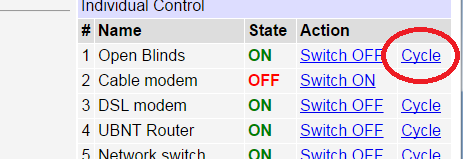
Click "Cycle"
Press the existing cycle button in
combination using the NC contact (instead of NO):
Custom Script
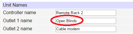
Name your circuit here:
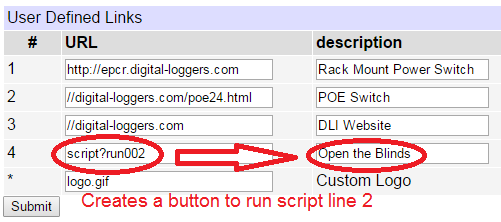
create a button that starts a script
starting on line #2:
 Clicking "Open the Blinds" toggles pulses the relay per this script:. 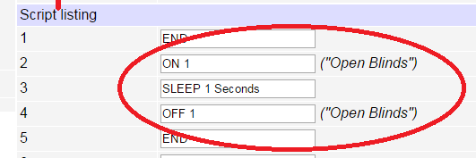
Try it at lpc.digital-loggers.com
admin/4321
You can also trigger scripts remotely. More
on that here.
Question: What's a relay? How can I wire it up? Answer: The DIN relay has dry contact FORM-C outputs. They provide whatever output voltage you connect to them. For example, if you connect a wire from the positive side of your 24V supply to the COM terminal, then the NO terminal will provide 24 volts when the relay is switched on, and the NC terminal will provide 24V when the relay is off. You can operate the DIN relay on a different voltage than the relay contacts. For example, the DIN relay could run on 12VDC, but switch 220VAC. You can also use the relay to switch data, phone lines, or other electrical signals. In a relay, contacts are electrically isolated from the coil. The DIN relay controls the coil in the diagram below:
N.O. means Normally Open
N.C. means Normally Closed
COM means COMmon
Each relay is fully isolated, there is no
internal connection between the relays.
A relay schematic looks like this:
Find relay basics here:
If we haven't answered your questions here, please call (408) 330-5599 or send us an email. We'll be glad to help. © Digital Loggers, Inc. 2005. |
||||||||||||||||||||||||||||||||||||||||||||||||||||||||||||||||||||||||||||||||||||||||||||||||
