Question:
Can I invert AutoPing or the Web Page to use NC contacts?
Answer: For safety reasons and to prevent support issues, we have not implemented an
"invert relay" function in either the web UI or AutoPing. You can
drive the relays in reverse by:
-
Setting up a
script to turn a relay -on- in the event of an AutoPing failure.
For example Line 2: "ON 1"
- Use the
AutoPing event to
trigger the script (enter the line number ie 2 of the script for that
Autoping IP).
You can also use the
programmable web links to start a script. For example, a link like
"CIRCUIT 1 OFF", could be lined to a script 2. ON 1, 3. END. This
inverts the "OFF" operation by closing the relay.
What is the current version of firmware?Answer: The current version is
on the update
page
Find the
revision history here, and
firmware
update instructions here.
Question:
What is the default IP address? How do I reset to defaults? What is the default
password?
Answer: If you
have lost the IP address or admin password,
follow this procedure to reset to the default IP address of 192.168.0.100:
Question: On initial setup, I can't establish a Ethernet communications
from a Windows PC. Help!
Answer: Follow
the instructions in this
document.
Question: Can you explain the auto-ping settings?
Answer:
Enabling auto-ping
To enable auto-ping, the check-box to the left of the IP address must be checked, then the change
button pushed. You will get a message "Autoping will automatically be enabled after 10 successful
pings". This prevents rebooting units before conditions are properly established.
Time Between Pings
The time between which each ping is set. The time between pings to a particular device
is (Time_Between_Pings * Number_of_devices_enabled_in_the_ping_list).
Ping failures before reboot
Number of times the ping has to fail (in a row) on a given device before
it is power cycled.
Ping responses to enable autoping (0-100 pings)
How many pings should be sucessful before enabling the autoping. This setting
prevents enabling autoping on an unreliable network and rebooting equipment
unnecessarily.
Times to attempt reboot
Number of times to attempt power cycling before giving up and disabling auto-ping.
Device reboot delay
Length of time after a power cycle before checking for a response from the device.
This allows a device or computer time to completely boot up.
Find a more
detailed description of Auto-Ping here. Find instructions on
modifying
Auto-Ping behavior using scripting here.
Question:
How can I control the switch from my
own applications?
Answer: Download
the latest User Utility which includes PowerMan support for
Linux. Your application can use HTTP communications.
Here are some examples
with source.
Users can use curl on any DLI power controller.
You can download
a Perl interpreter to run the script version. This script is
compatible with all DLI power controllers.
Question:
Can you
develop custom firmware for my application?
Answer:
Gladly. We've done this for many customers. Our programming rate
is $75/hour. After we agree on a -very specific- project description,
we can send you an estimate of the time involved to code, debug and test.
Question: Can you develop custom hardware
for my application?
Answer:
Gladly. We've done this for many customers. Please call with your requirements
Question: Do
you support PowerMan?
Answer:
Yes, absolutely. The latest code is here: Download
the latest User Utility here.
Question:
How can I momentarily trigger (pulse) a relay?
Answer: Three
examples:
Hardware
Just wire a capacitor in series with the
circuit (assuming a DC load). Simple.
Click "Cycle"
Press the existing cycle button in
combination using the NC contact (instead of NO):
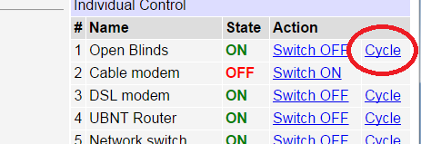
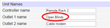
Custom Script
Name your circuit here:
create a button that starts a script
starting on line #2:
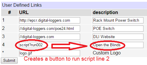
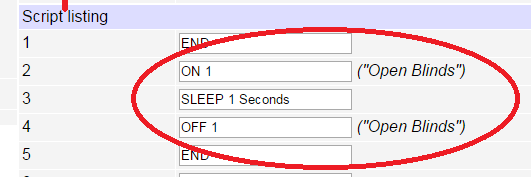
Clicking "Open the Blinds" toggles pulses the relay per this
script:.
Try it at lpc.digital-loggers.com
admin/4321
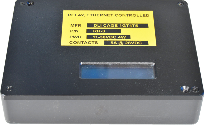
Question:
What's a relay? How can I wire it up?
Answer:
The Rugged Rebooter relay has dry contact outputs. They provide whatever
output voltage you connect to them.
For example, if you connect a wire
from the positive side of your 24V supply to the COM terminal, then the
NO terminal will provide 24 volts when the relay is switched on, and the
NC terminal will provide 24V when the relay is off.
You can operate the
RR3 on a different voltage than the relay contacts. For example,
the Rugged Rebooter relay could run on 12VDC, but switch 24VDC. In
a relay, contacts are electrically isolated from the coil. The RR3 controls the coil in the diagram below:

N.O. means Normally Open
N.C. means Normally Closed
COM means COMmon Each relay is fully isolated, there is no
internal connection between the relays.
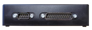
You can find the pinouts here.
A relay schematic looks like this:
Back To Top

If we haven't answered your questions here, please call (408) 330-5599 or send
us an email. We'll be glad to help.
© Digital Loggers, Inc. 2005-2021
|