Frequently Asked Questions
Updated 3/28/2025DIN 4
Quick-start user's guide •
Complete Documentation •
Check the specs
Firmware Update •
What accessories are available?
See the overview here - or call (408) 330-5599 for a free trial
Setup
Is there a keypad reference?
How do I set up network with the keypad?
How do I set up the WiFi network?
How do I set up network access in Windows? From a Mac? - Thanks to John McClintock for these Mac tips.
How do I set up port forwarding? Router Port Forwarding example. - Kudos to Mike G
What is the default IP address? How do I reset to defaults? What is the default password?
Where can I find the most complete help and documentation?
Hardware
How can I control
higher-current loads?
What is the polarity of the connectors?
How can I power the
DIN relay itself?
Basics: What's a relay?
How can I wire it up? Do you have a
mechanical drawing?
How do I connect the ADC inputs?
What are the connector
specifications?
What is the
power dissipation?
What are the
power requirements?
What pluggable mating terminals / connectors should I use?
What wiring gauge should I use?
I'd like to build a DC / solar powered IP Cam, WiFi AP, or similar DC powered system. What components do I need?
What are the contact ratings?
What wire should I use?
Where are the safety fuses located?
Do you have a ruggedized version? Something suitable for mobile use?
* Please note that the built-in Help is quite extensive and specific to the firmware version. We encourage you to explore it.
E.g. http://pro.digial-loggers.com:5002/ Credentials: admin / 4321
General FAQs
Where can I find the manual or spec sheet for the earlier (DIN3) model?
What is the current version of firmware?
Can you develop custom firmware or custom hardware for my app?
What are the CRITICAL and PROTECT functions?
Where can I find more extensive and detailed help?
How can I set up autoping to reboot my modem and router, but have my router to come on later?
Can I set outlets to cycle at different rates?
Can I increase the internal system log size?
How can I get a dry contact relay output?
What's the new Lua Language and Scripting all about?
How can I control and customize the LCD?
How do I enable autoping? Explain the autoping settings
What's syslog? How can I keep an event log?
How do I set up event notifications?
How do I change the NTP servers?
The session timeout is too short. Can I make the session longer?
What is the command-line interface in the SSH shell?
How can I update the firmware via the SSH shell?
How do I install a supported VPN?
How can I use the Ubiquity Dream Machine VPN? Thanks to William Dedic for these instructions.
How can I clean up old SSL certificates?
How can I install my own certificate?
Fixes
How do I fix: email notification failed: [CURL-EASY][PEER_FAILED_VERIFICATION] SSL peer certificate or SSH remote key was not OK (60)
How do I fix: email notification failed: [CURL-EASY][COULDNT_RESOLVE_HOST] Couldn't resolve host name (6)?
I can't access the controller from another network. Cannot autoping an external server such as 8.8.8.8. How do I fix cross network access?
How do I fix: [CURL-EASY][OPERATION_TIMEDOUT] Timeout was reached (28)? Check the above 3 issues.
How do I fix: Peer certificate cannot be authenticated with given CA certificates (60)?
How do I fix: "failure while reading service directory" when trying to renew a SSL certificate?
When I unplug the Ethernet cable the WiFi quits working.
How do I clear "SECURITY LOCKOUT IN PLACE" when I try to login?
How do I fix a "Host request header not present or not recognized" error when I try to login from a different network?
I am getting "Rejected request from RFC1918 IP to public server address".
I am getting "Possible DNS-rebind attack detected". How do I disable DNS-rebind protection?
External APIs - Communicating with the power controller
How can I connect to Amazon Echo, Alexa, Dot or Tap products?
How can I connect to Google Assistant or Google Home?
How can I access the switch from my own application or remote script? What's the cURL API?
Is this product compatible with legacy plaintext scripts and HTTP control?
How can I control the switch from my own applications?
What is the recommended REST API?
Can I give a non-admin user limited admin access?
Have any SNMP setup tips?
Do you support MQTT?
How can I set up IFTTT?
Do you support HomeSeer?
Do you have a Crestron control module?
Can I use LabVIEW to control DLI power controllers?
Where can I find ASCOM drivers?
Do you have a Visual Basic.NET example program? Thanks to Alan Holmes
Do you have a .NET programming example?
Do you have a Java programming example?
Do you have a compiled Windows command line tool or a Perl example?
Do you have a Python programming example?
How can I run a Perl script from LabView?
Here is a Ham Radio Users Group video: Node-Red Tutorial - Digital Loggers Web Power Switch Pro Flow Explained!
Do you support OPC UA (IEC 62541)?
Where can I find iPhone, iPad, or Android apps for Digital Loggers?
Do you support PowerMan?
| Question: | I have a different model: DIN2,DIN3, Web Power Switch 7, Ethernet Power Controller II, III, V, or PC-8000 model. Where can I find information? |
| Answer: | Jump to the support page here. Don't see what you need? Just give us a call (408) 330-5599. |
| Question: | What's the Hardware Revision History? |
| Answer: |
In our second version, DIN Relay II, with serial numbers DIN22000 and higher,
we added these features:
In of DIN Relay III, we added these features:
In version 3.1, we added these features:
In version 4, we completely redesigned the unit and added a host of new features:
Note: version 4 supports input supply voltages from 12 to 28VDC. If you require 48V or AC mains power, please contact sales for a variant product. RS-232 has been removed in lieu of the sensor port and ADC inputs.
Tell us what you'd like to see in the next version - engineering@digital-loggers.com |
| Question: | Whch temperature sensors are compatible? |
| Answer: |
The DS18B20 or DHT-11 sensors with
RJ12 plugs are compatible and in stock.
Find a Lua thermostat code example here. The sensor port is an ESD protected TTL level bidirectional port. The RJ-12 jack is wired for connections suitable for Dallas 18B20 or DHT11 style sensors. Pins 1&2 are +5V power out, Pin 3 is the bidirectional TTL data bus. Pin 4 is grounded. 5V current is limited to about 50mA. The power controller will automatically detect the attached sensor. |
| Question: | What is the polarity of the connectors? |
| Answer: |
The polarity is stamped above the conenctor. It may be eeasier to see if they are removed.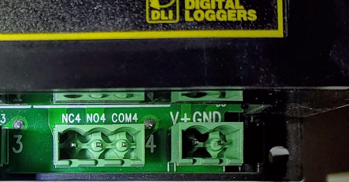 |
| Question: | What are the contact ratings? | ||||||||||||||||||
| Answer: |
All eight internal T-90 Relays have the following ratings:
Relays are rated at 250,000 operations MTBF at 50% load. Case terminals are rated at 8-12A, depending on agency. Only stranded wire of appropriate gauge should be used. Terminals must be well torqued, but not over 10in/lbs. It is wise to recheck torque after completing the installation. Heavy traces and gold plating are used to minimize internal resistance between the terminals and relay contacts, typically 25m Ohms, so internal contact power dissipation is not normally a consideration. For maximum flexibility, relay contacts are unprotected. For high current inductive switching, consider adding an external snubber circuit to extend contact life. Download contact protection information from relaycare.pdf |
||||||||||||||||||
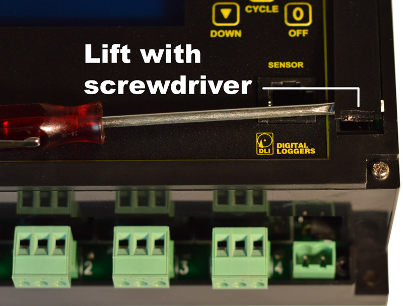
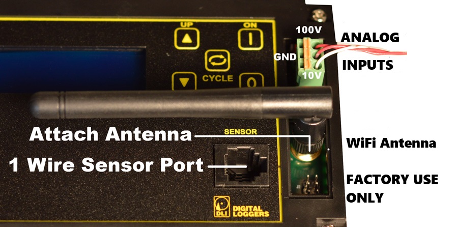
| Question: | How do I connect the ADC inputs? |
| Answer: |
Remove the accessory hatch. The plastic hatch on the right side of the relay can be opened to add a WiFi antenna or to connect analog inputs.
Using a small screwdriver, press gently on the lower edge of the hatch. Push towards the buttons The hatch will flex and pop open.
The antenna and/or ADC connector may be attached when the hatch is removed. A three pin connector is provided for ADC input. The upper pin is scaled for 0-100VDC, and the lower pin is 0-10VDC. The center pin is a ground reference bonded to the negative power input.
|
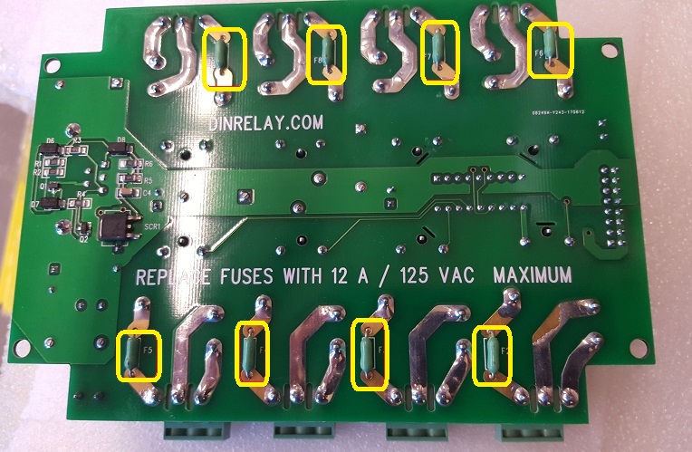
| Question: | Where are the safety fuses in the unit? |
| Answer: |
On the bottom of the relay circuit
board are over-current protection fuses on all relay common lines for safety. If one of these fuses blow, the relay will still "click", but power will not pass through.
They are 12A fast-blow fuses. Fuse specs are here.
P/N DIN4-FUSE 10-pack available from DLI $7.95. Call 408-330-5599 option 1 to order.
|
| Question: | How can I momentarily trigger (pulse) a relay? |
| Answer: |
Three Examples: Hardware Just wire a capacitor in series with the circuit (assuming a DC load). Simple. Click "Cycle" Press the existing cycle button in combination using the NC contact (instead of NO): 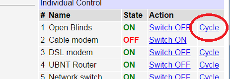 Custom Script Name your circuit here: Create a button that starts a script starting on line #2: 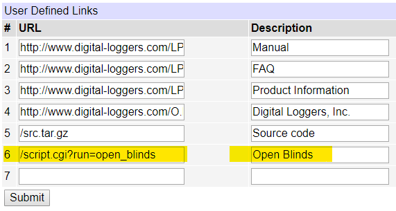 Clicking "Open the Blinds" toggles pulses the relay per this script:. -- Open the Blinds function open_blinds() outlet[1].on() delay(1) outlet[1].off() endTry it at pro.digital-loggers.com:5002 admin/4321 You can also trigger scripts remotely. More on that here. REST API and MQTT. The BASIC scripting language has been replaced by Lua. A much more powerful watchdog supervisory processor has been added. Most important, there's good news on price: the new, more powerful ICs are less expensive. Here's a feature matrix comparing the older Taifatech and newer Atheros power models. |
| Question: | Can I invert AutoPing or the Web Page to use NC contacts? |
| Answer: |
or safety reasons and to prevent support issues, we have not implemented
an "invert relay" function in either the web UI or AutoPing.
You can drive the relays in reverse by:
You can also use the programmable web links to start a script. |
| Question: | What are the mounting dimensions and physical size? Do you have drawings? |
| Answer: | Download a top-level print here (.pdf). Here are graphics of the front of the relay. |
| Question: | What components do I need to build a remotely powered DC site using the DIN relay as a power controller? |
| Answer: | In addition to the load (ie. APCam, PtP link, AP, etc), you'll need a battery, some source of power, ie wind or solar, and most importantly a charge controller with OVP and UVLO features. Over Voltage Protection is needed for reasonable battery life. Under Voltage Lockout is needed to correctly reset attached devices as well as the DIN relay and to prevent oscillation when the battery is deeply discharged. |
| Question: | Wiring and terminal information? |
| Answer: | Use stranded wire from 28AWG to 14AWG. Find information on Phoenix connectors here. |
| Question: | What's a relay? How can I wire it up? |
| Answer: |
The DIN relay has dry contact FORM-C outputs. They provide whatever
output voltage you connect to them. For example, if you connect a wire
from the positive side of your 24V supply to the COM terminal, then the
NO terminal will provide 24 volts when the relay is switched on, and the
NC terminal will provide 24V when the relay is off. You can operate the
DIN relay on a different voltage than the relay contacts. For example,
the DIN relay could run on 12VDC, but switch 220VAC. You can also use
the relay to switch data, communications lines, or other electrical signals. In
a relay, contacts are electrically isolated from the coil. The DIN
relay controls the coil in the diagram below:
N.O. means Normally Open
N.C. means Normally Closed
COM means COMmon Each relay is fully isolated, there is no
internal connection between the relays. The word "common" describes
the wiper of the relay itself which shares the NO and NC contacts in common. The COM pins on the DIN
relay are not connected each other unless you elect to do so
externally. Put simply, all relays are fully isolated.
A relay schematic looks like this:
Find a nice group of relay application notes and wiring examples here: https://www.digital-loggers.com/relay.html |
| Question: | What is the current version of firmware? |
| Answer: | Find the revision history here, and firmware update instructions here. |
| Question: | How does this model compare to the earlier wired-only models? |
| Answer: | These units have both hardwired Ethernet and WiFi, thanks to a more powerful 32 bit CPU from Qualcomm Atheros. The design includes expanded memory for the Atheros including FLASH, EEPROM, and SDRAM. Leveraging open-source code and expanded memory allowed us to add several firmware features including SNMP, HTTPS, SSL, SSH, a REST-like API, Alexa Compatibility and MQTT. The BASIC scripting language has been replaced by Lua. A much more powerful watchdog supervisory processor has been added. Most important, there's good news on price: the new, more powerful ICs are less expensive. Here's a feature matrix comparing the older Taifatech and newer Atheros power models. Courtesy of Mike Gillen |
| Question: | Where can I find more extensive and detailed help? |
| Answer: |
Click on the Help menu link on the power controller itself.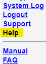 Then click on the on-line help icon.  |
| Question: | I have a different model: Web Power Switch 7, Ethernet Power Controller II, III, V, or PC-8000 model. Where can I find information? |
| Answer: | Jump to the support page here. Don't see what you need? Just give us a call (408) 330-5599. |
| Question: | How can I control and customize the LCD? |
| Answer: | The LCD can be used to display settings, outlet status, or any message of your choice. You can operate the LCD in "billboard" style, displaying a series of user defined messages. To customize the LCD, you'll want to write a script using the Lua scripting language. You can also use the display to send messages from remote systems (ie. service alert warnings). To send messages remotely, write a script first, saving it in FLASH then start the script from your remote system. Learn more about scripting here. |
| Question: |
How can I set up autoping to reboot my modem and router, but have my router come on later? Can I set outlets to cycle at different rates? |
| Answer: |
OF course, this can be done via Scripts. However, you can also make the outlets cycle at individual rates by using the REST API or UOM. Log into the power controller and be sure that the REST API is enabled. Go to the Outlets in the REST API. e.g. http://192.1680.100/restapi/relay/outlets/ Select the outlet to set the custom cycle time on. 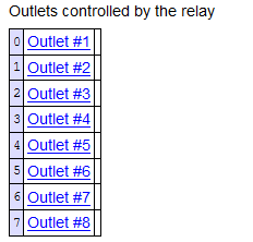 Select the cycle delay setting. 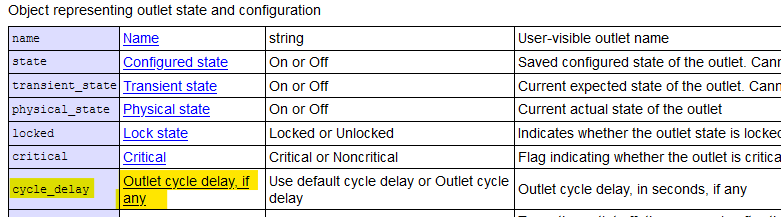 Set the custom cycle delay.  For example, you can set the modem delay to 15 seconds and the router delay to 45 seconds. In this example, when Autoping cycles the outlets, the modem will come on after 15 seconds and the router will come on after 45 seconds. |
| Question: | Is this product compatible with the older (less secure) HTTP plaintext command syntax? |
| Answer: |
To use the earlier
HTTP commands
described here and
CURL scripts that use plaintext login, you'll need to enable this
legacy setting on the SETUP page:
|
| Question: | What is the default IP address? How do I reset to defaults? What is the default password? |
| Answer: |
Follow this procedure to reset to the default IP address of 192.168.0.100:
Press and release the reset button. After about 5 seconds, you will hear a beep, then use the up The following reset modes are available: 1. Clear lock bits: Clear protection bits only. Other settings are
preserved. The default master login is "admin" and default password is "1234". The default IP is 192.168.0.100. If all settings are reset (the two last 'wipe' reset modes), the Subnet Restriction will be enabled to prevent remote access using the default password. ONLY MACHINES IN THE SAME SUBNET WILL BE ABLE TO CONNECT AFTER RESETTING TO DEFAULTS. Besides setting your computer to a compatible network, you can also use the keypad to set it up. The keypad settings Pro/V222/DC3/ISO32 are slightly different from the keypad settings for the DIN and EPCR models. |
| Question: | On initial setup, I can't establish a Ethernet communications from a Windows PC. Help! |
| Answer: |
If your default Windows settings won’t access the controller,
follow
these steps to reach the controller’s IP. You'll find a
more extensive explanation
in the user's manual.
Details for setting
up via the keypad can be found here. Before adding an IP, close network programs and browsers. Go to the Network Settings – Local Area Network or use the keyboard shortcut
( <Windows-R> - in the Run... box type “ncpa.cpl” and click OK
). The default user name is "admin" (lower case) and password is “1234” Set the IP address of the unit to your network, then restore your settings. |
| Question: | How can I change the NTP servers? |
| Answer: |
Log into the unit and choose the External APIs link. If the REST API is not enabled, check the REST API checkbox and press submit. Either: Scroll down to the "Browse the REST API" link Select config Select ntp_peers or enter it manually Eg: http://192.168.0.100/restapi/config/ntp_peers/ Now you can select NTP peer #1 and edit it |
| Question: | Can I set the session timeout longer? |
| Answer: | Yes Log into the unit and choose the External APIs link. If the REST API is not enabled, check the REST API checkbox and press submit. Scroll down to the "Browse the REST API" link <strong>or enter it manually Eg: http://192.168.0.100/restapi/ Select the auth (Authentication server object) link Select Cookie timeout Eg: http://192.168.0.100/restapi/auth/cookie_timeout/ Enter a time in seconds. The next time you login, the timeout will take effect. |
| Question: |
Can I increase the internal system log size? |
| Answer: | Yes, but this must be done using the SSH shell. Log into the unit via SSH. The default is 16KB; to make it 64, use these commands: uci set system.@system[0].log_size=64 uci commit system /etc/init.d/log restart *Note that this will clear the log. |
| Question: | How to I install a supported VPN? | |||||||||||||||||||||||||
| Answer: |
Instructions and information are in the built-in Help under User-installable packages. Also in the Complete Online
Documentation - User's Guide under User-installable packages. Below are basic instructions for Tailscale, ZeroTier, NetBird, innernet and OpenVPN. For others, please check the Help in the power controller. These must be installed and configured using SSH. See Help for more information.
ZeroTier: First, if you do not have one, prepare a ZeroTier account. You need to log into their site, create a network and take note of your Network ID. Then log into the power controller via SSH and run: cd /tmp opkg update opkg install zerotier Then either edit the existing sample network in /etc/config/zerotier to have the network ID match the one you have taken note of, or create a new network by running the commands below, replacing 0123456789abcdef with your Zerotier network ID: uci set zerotier.openwrt_network=zerotier uci add_list zerotier.openwrt_network.join='0123456789abcdef' uci set zerotier.openwrt_network.enabled='1' uci commit zerotier After editing the configuration, run: /etc/init.d/zerotier restart The device will appear in the net in the zerotier web UI control panel but isn't authorized (and thus has no IP). Tick the Auth checkbox, and it will gain an IP. Steve Young brought these alternative instructions written by Reg Pratt to our attention. *The configuration is retained across firmware updates. The package must be reinstalled after firmware updates unless the firmware is 1.13.1.0 or higher and the "Preserve user installed packages" is checked in the Firmware Upload page before the update. Tailscale: FIRST, if you do not have one, prepare a Tailscale account cd /tmp opkg update opkg install tailscale-combined tailscale up You will be prompted to authorize the device (copy the URL and paste into the browser): *The configuration is retained across firmware updates. The package must be reinstalled after firmware updates unless the firmware is 1.13.1.0 or higher and the "Preserve user installed packages" is checked in the Firmware Upload page before the update. ** Tailscale Notes: We ship with trimmed-down versions that may be seriously out of date, but are not necessarily vulnerable despite vendor warnings. Some of the features that we remove may also remove the venerability. We recommend that you check https://tailscale.com/security-bulletins for security concerns. NetBird: FIRST, if you do not have one, prepare a NetBird account AND verify the email (activation will otherwise fail). cd /tmp opkg update opkg install netbird netbird up You will be prompted to authorize the device (copy the URL and paste into the browser) *The configuration is retained across firmware updates. The package must be reinstalled after firmware updates unless the firmware is 1.13.1.0 or higher and the "Preserve user installed packages" is checked in the Firmware Upload page before the update. ** NetBird Notes: We ship with trimmed-down versions that may be seriously out of date, but are not necessarily vulnerable despite vendor warnings. Some of the features that we remove may also remove the venerability. We recommend that you check https://netbird.io/ for specific security concerns. Innernet summary: (requires 1.12.9.0) This release includes two new installable packages, innernet and innernet-server supporting, as of now, Linux and Mac OS only (no Android, Windows, etc.). They enable you to build kernel-mode-routed mesh networks based on the Wireguard protocol, but there's no central server: you need to host it yourself by installing "innernet-server" on a device with a public IP, installing "innernet" and following the documentation (both packages have a text-mode user interface for configuration). The summary is that it may be tricky to configure and limited to UNIX-like systems, but shaves off ~15% of median ping time, reduces RAM usage and CPU load, and isn't controlled by third parties. OpenVPN: cd /tmp opkg update opkg install openvpn Edit the /etc/config/openvpn file https://openwrt.org/docs/guide-user/services/vpn/openvpn/client /etc/init.d/openvpn start *The configuration is retained across firmware updates. The package must be reinstalled after firmware updates unless the firmware is 1.13.1.0 or higher and the "Preserve user installed packages" is checked in the Firmware Upload page before the update. |
| Question: |
How can I clean up
old certificates from prior firmware versions? |
| Answer: | Beginning with firmware 1.12.14.0, you can get a list of certificates not shipped with the
current firmware via the RESI API. http://192.168.0.100/restapi/config/certificates/all;custom=true/ or curl e.g.: curl -u admin:1234 -H "Content-type: application/json" --digest http://192.168.0.100/restapi/config/certificates/all;custom=true/ You can delete selectively via SSH or the REST API. To delete all certificates not shipped with the current firmware via curl e.g.: curl -u admin:1234 -X DELETE -H "X-Requested-With: XMLHttpRequest" --digest http://192.168.0.100/restapi/config/certificates/all;custom=true/ Alternatively, a full reset will clear them. Perform a complete backup, except uncheck the "Trusted certificate and revocation list store". Perform the full reset (complete wipe). Restore from backup. |
| Question: |
How can I install my own certificate? |
| Answer: |
Your certificate and key must be in PEM format with the certificate being the full chain.
Once created, login via SSH and place them into /etc/uhttpd.key and /etc/uhttpd.crt,
respectively. |
| Question: | When I unplug the Ethernet cable, WiFi quits working. |
| Answer: |
This happens when the Wired and WiFi are on the same network and subnet. 1. Change the LAN Metric to 1. This resolves most of these issues. (Firmware 1.9.8.0+) 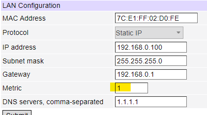 If you plan to run the WiFI and Ethernet on the same network continually or still have issues; 2. Change the last character of the WiFi MAC address. e.g. http://192.168.0.100/restapi/network/wireless/mac_address/ 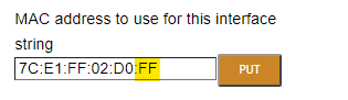 Changing the last HEX number is all that is required. |
| Question: | How do I fix: email notification failed: [CURL-EASY][COULDNT_RESOLVE_HOST] Couldn't resolve host name (6)? |
| Answer: |
1. Verify that "Same subnet only" is unchecked in the General Network Settings 2. Verify that a gateway is entered in Network Settings 3. Verify that a DNS server are entered in Network Settings |
| Question: |
How do I fix: [CURL-EASY][PEER_FAILED_VERIFICATION] SSL peer certificate or SSH remote key was not OK (60), Peer certificate cannot be authenticated with given CA certificates (60) or Certificate renewal error "failure while reading service directory". |
| Answer: |
If the firmware version is below 1.9.x, then update the firmware to support the latest certificates. If the issue persists, log into the unit via SSH. Type: curl --capath /etc/ssl/certs/ https://acme-v02.api.letsencrypt.org/directory If you get "curl: (6) Could not resolve host: acme-v02.api.letsencrypt.org" then verify that the DNS server(s) are set in setup/networking. If you get "curl: (60) SSL certificate problem: unable to get local issuer certificate More details here: https://curl.se/docs/sslcerts.html" then type: ls -l /etc/ssl/certs/ You'll likely see the .crt files but no symlinks like 12345678.0 -> XXX.crt. If so, then type or copy/paste: rm -f /etc/ssl/certs/[0-9a-f]*.[0-9] uci delete system.__dliconf_trust_all_known_root_ca_certificates uci commit system sh /rom/etc/uci-defaults/trust-all-known-root-ca-certificates uci: Entry not found < -- This is normal then check that ls -l /etc/ssl/certs/ shows the symlinks have appeared. |
| Question: | How do I clear "SECURITY LOCKOUT IN PLACE" when I try to login? |
| Answer: |
When you enter an incorrect password or use an old "hidden key" too many times, you may be *locked out. In the Settings page is a "Delays" section. The duration of the security lockout is set there: 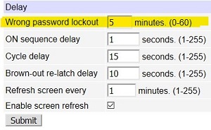 There are a few ways to end the lockout. Option A. Don't access the unit until the lockout expires There are three ways to end the lockout prematurely without power-cycling. Option B. Press the reset button and choose option 1 or option 6: Press and release the reset button. After about 5 seconds, you will hear a beep, then use the up The following reset modes are available: 1. Clear lock bits: Clear protection bits only. Other settings are
preserved. Option C. Login via SSH and type: reboot Option D. Login via SSH and type: /etc/init.d/generic_state_server restart * To help prevent lockouts: With each visit to the login page a secret key is generated. If another key is generated because someone else brought up the page after you did, then the key has expired. Before logging in, press the F5 key to refresh the browser if it has been some time since going to the login page. If you make a mistake on the password and press the "back" button on the browser to go back and try again, press F5 to refresh the page and get a new key. If you don't do this, you are using the old key and will get locked out. |
| Question: | How do I fix a "Host request header not present or not recognized" error when I try to login from a different network? |
| Answer: |
Firmware 1.12.12.0+ supports "Host request header filtering for DNS rebinding protection". Login via a local IP address and check the "Allowed Hostnames setting in the general network settings section. If the top field empty, enter an asterisk ( * ) in and submit the changes. For better security, see below: 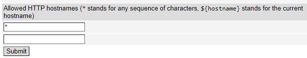 If the unit is accessible only via a private (e.g. RFC1918) IP address, a malicious site can manipulate its DNS entry to trick your browser into sending a request to the private address. Host header restriction can used to prevent such DNS rebinding attacks. The default permitted list contains just the wildcard "*" for backwards compatibility. To enable the protection, add patterns for hostname(s) you use to address the unit to the list and remove the "*" wildcard. AFTER REMOVING THE "*" WILDCARD, THE UNIT MAY ONLY BE REACHED VIA HOSTNAMES MATCHING THE PATTERNS LISTED, OR BY ITS LOCAL IP. If connectivity is lost, use a local connection as discussed above and use the explicit IP address, which always is an allowed Host header value. Hostname patterns support the following special sequences: "*" stands for any sequence of characters, e.g. "*.example.com" will match "pcr.example.com" and "another.pcr.example.com"; "${hostname}" stands for the current unit hostname (as configured), and will usually be used for as part of a fully-qualified domain name (e.g. "${hostname}.example.com") for uniform configuration between several units. |
| Question:/i> | My program used to run fine on an earlier model, but won't run on this one. What can I do? |
| Answer: |
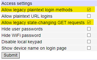
It's possible that the program requires legacy login methods
which accept plaintext authentication. Go
to the Setup page and tick the "Allow legacy plaintext login
methods" checkbox, then click "Submit". If the program works, please inform the author that the preferred authentication method is by using the more secure challenge/response mechanism. Have a look at the Rest API here for new development. |
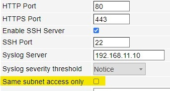
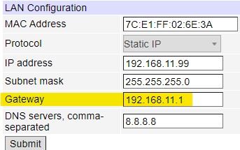
| Question: | I can't access the controller from another network. Autoping will not ping an external server such as 8.8.8.8. How do I fix it? |
| Answer: |
1.
First make sure the
"Same subnet access only" is unchecked in the General network settings
#route
Kernel IP routing table
Destination    Gateway         Genmask        Flags  Metric  Ref  Use  Iface
default        192.168.11.1    0.0.0.0         UG      0      0    0   eth0
192.168.11.0   *              255.255.255.0   U       0      0    0   eth0
Only if you don't see a default route and items 1 and 2 are verified, enter these commands into the SSH shell. /etc/init.d/default_route_manager stop /etc/init.d/default_route_manager disable rm /etc/udhcpc-filters/500-divert-default-route-updates /etc/init.d/network restart *Let support@digital-loggers.com know that these default_route changes were made. |
| Question: | How do I fix: Rejected request from RFC1918 IP to public server address? |
| Answer: |
Log in via SSH and run theese commands: uci set uhttpd.main.rfc1918_filter=0 uci commit uhttpd /etc/init.d/uhttpd restart If it still does not work, type: reboot |
| Question: | How do I disable DNS-rebind protection? |
| Answer: |
Log in via SSH and run theese commands: uci set dhcp.@dnsmasq[0].rebind_protection=0 uci commit dhcp /etc/init.d/dnsmasq restart To re-enable protection: uci set dhcp.@dnsmasq[0].rebind_protection=1 uci commit dhcp /etc/init.d/dnsmasq restart |
| Question: | Can you develop custom firmware for my application? |
| Answer: | Gladly. We've done this for many customers. After we agree on a -very specific- project description, we can send you an estimate of the time involved to code, debug and test. In most cases, a kick-off meeting in Silicon Valley is required. |
| Question: | Do you support HomeSeer? |
| Answer: |
Yes!
Alex Khassapov has created a
plugin for HomeSeer. |
| Question: | Do you support OPC UA (IEC 62541)? |
| Answer: |
Yes! OPC UA support was added in firmware 1.15.6.0. Check the built-in help or the users guilde in the online documentation in the External APIs section. |
| Question: | Can you develop custom hardware for my application? |
| Answer: | Gladly. We've done this for many customers. Please call with your requirements. To amortize NRE, practical minimum order quantities are typically 100-1000 units. In most cases, a kick-off meeting in Silicon Valley is required. |
| Question: | Do you support PowerMan? |
| Answer: | Yes, absolutely. The latest code is added to the tarball. Download the latest User Utility here. |
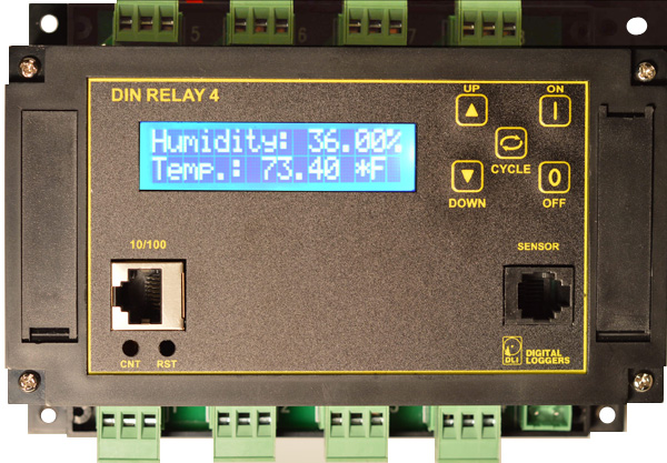
| Question: | What is the blue LCD for? |
| Answer: | The blue LCD shows outlet status during power up, the IP address, netmask, outlet names, and other useful information. Time and date stamps for significant events (such as power outages or emergency shutdowns) are also displayed. Using the keypad, you can set up some of the features such as the network settings. You can program this display to display your own messages using the scripting feature. |

If we haven't answered your questions here, please call (408) 330-5599 or send us an email. We'll be glad to help.
© Digital Loggers, Inc. 2005-2024.